Week 13: Output Devices

Wednesday 27/04/16 was a big national holiday for the Netherlands so decided to go out to experience what 'Koningsdag' is, instead of joining the local review in the morning :-) In any case Niewmarkt where Fab Lab Amsterdam is situated was almost inapproachable by the people celebrating the king's birthday and the class was not going to meet there. At least I got two summer dresses for €4 because that's what you do on King's day - drink and buy cheap stuff. All that is left is to wait for the summer to appear so I can wear my dresses!
On Thursday 28/04/16 we arranged to see Neil's lecture from the previous day and later join Emma's Lecture on Output Devices. I was able to follow some subjects more than others, but in the end I have decided that it is time to do some filtering as to what it is I need to gain from each class while I am here. One simply cannot absorb everything in such a little time! For this assignment I have decided to use Neil's example of the speaker as a way of working towards my final project. I have changed my mind from doing the insence burner and I am aiming to make a chair that talks to you once you sit on it. It will be saying politically incorrect messages that politicians (in Cyprus and abroad) have said over the years. I will need the recordings and somewhere to store them, some microcontrollers and a few other electronics elements, possibly some better speakers and a flawless code, but Emma said that the'hello-speaker' example would be a good start, so I am going for it!
What is important to 'keep' from this week is that:
- 1mA will do no harm to a person
- 10mA will cause a minor shock
- 100mA can kill you!
VGS is just the Voltage from gate to source. The absolute maximum VGS is the maximum voltage you should ever subject the mosfet to under any conditions (stay well away).
Capasitors can store energy for up to one year so one should be very careful when handling such devices especially when they don't know where they chave come from.
A Transistor is a semiconductor device used to amplify or switch electronic signals and electrical power. It is composed of semiconductor material with at least three terminals for connection to an external circuit.
A Mosfet is a field-effect transistor in which there is a thin layer of silicon oxide between the gate and the channel.
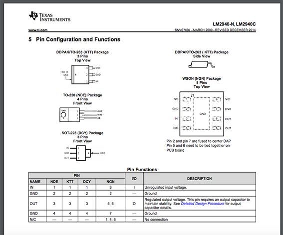
A voltage Regulator is designed to automatically maintain a constant voltage level. A voltage regulator may be a simple 'feed-forward' design or may include negative feedback control loops. It may use an electromechanical mechanism, or electronic components.
On Friday 29/04/16 I was determined to draw up a schematic and a board completely by myself. I was designing the example that Neil gave on his lecture in combination with an 'example' that Emma gave to us in her lecture. I spent quite a bit of my day on it and I was successful up to a decent point, I believe. I got stuck on how to name and add value to the schematic elements. Also on an FTDI symbol from Emma's notes which did not seem to be the same as the one in the Eagle Library.
To my disappointment, I had to go to the Fab Lab and get some help. I also needed a confirmation that I was moving to the right direction, because my questions were actually quite simple to answer and I knew it, but for some reason I still cannot easily find a straight-forward answer online regarding Eagle. It is also very awkward and frustrating to use new interfaces. Simple things that you know would work in other applications like 'select all' an simply unresponsive in Eagle!
So the solution to my problems was that:
- Firstly there needed to be a 'wire' connected to something before being able to name it…
- Then I needed to 'Name' my element and run the 'Label' command after that. Only then the name would show
- The FTDI cable element was in fact ok to use even though it was different than the one on Emma's notes
Crisis over.
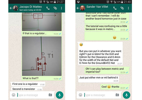
Saturday 30/04/16 I proceeded to generate the board from the schematic and I really wanted to give the autoroute command some more time. Some questions I had where answered very nicely by my two colleagues Sander Van Vliet and Jacopo Di Matteo.
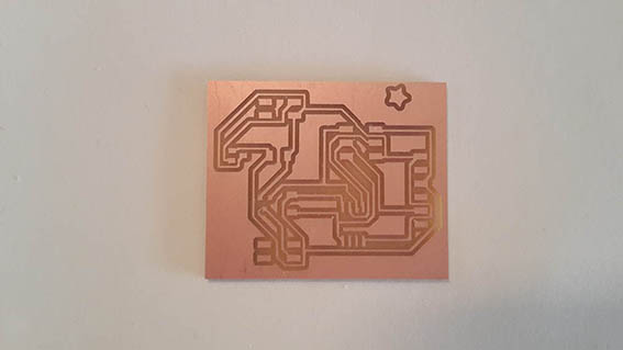
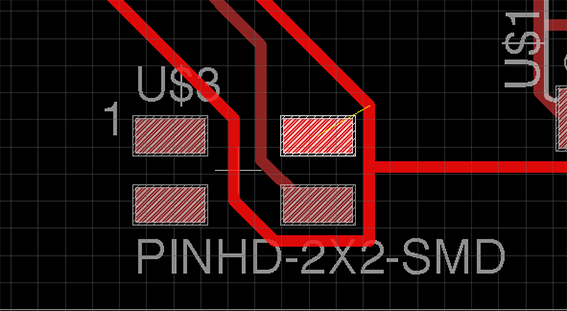
I did watch the tutorial that Emma had sent to us in the previous weeks as I did in Input Devices week but I was not completely satisfied. My traces seemed too thin for milling and I was worried that they were not going to come out ok. In the above image, the grid is set to 1mm and one can see two paths running inside it. The endmill is 0,39mm so there was no way they would be milled. I knew that there was a way to make the traces wider and the spaces between them also wider so I tried some internet searches here and here but without much luck. I also went through quite a bit of this tutorial only to be panicked about how complicated a pcb can be!
The positive side of this day was that I was able to export the .png file and it's border, take it through photoshop and get it ready for the modela without needing to read the 'how to export' tutorial any more!
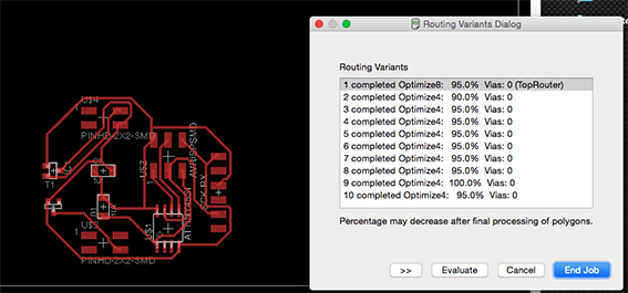
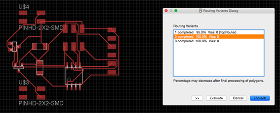
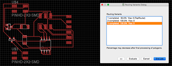
Sunday 01/05/16 Amid cleaning and re-arranging the house since my house-mates moved out, the goal was to master the autoroute command to get wider traces. I carefully watched the original routing tutorial and made more sense of the routing command.
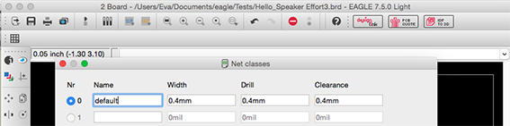
I set my net classes dimensions to 0,4 which is roughly the size of the endmill. That way there is no reason why something will not mill (but I only understood this now!) I also toyed around with the options given when actually performing 'autoroute'.
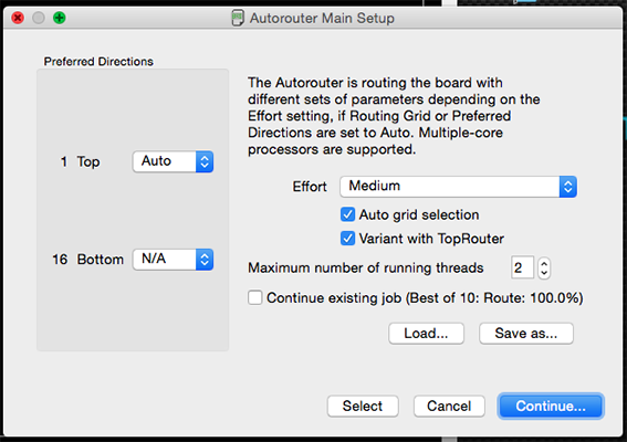
I quickly realized that unchecking the 'auto-grid selection' can really mess up the distances between the paths so I stuck to it and I managed to complete my goal of getting those wider traces.
Monday 02/05/16: After I had milled two successful boards and since I still had time on the Modela I decided to run my 'suspiciously thin traces' board just to confirm that they would not be milled correctly. I am very glad that I did, because that was what gave me the understanding of why less than 0.4 is unmillable. The imperial system does not help sometimes. I needed to go through that to understand that 1/32 = 0,39mm and that when setting the modela to 1/32 you are actually defining the size of the endmill!
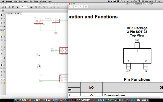
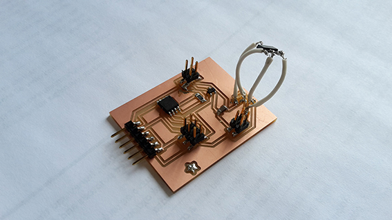
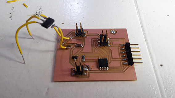
I proceeded to stuff the board after double checking the orientation and pin-out of the transistor and resistor in their datasheets, which was actually something that could have been done before milling… Thankfully, everything was ok so I started to solder some of the components on. This was not going as smoothly as I expected because the fine tip soldering iron was taken. It is funny how a person can get used to a particular tool and not be able to switch to another very easily.
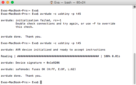
Nevertheless, soldering is not a big issue for me any more, nor is checking the paths and connections with the multimeter. I hope that this will still remain the case! I stuffed both boards and I ran the 'avrdude -c usbtiny -p t45' command which confirmed that the microcontroller was readable and programmable.
That was when I realised that something was smoking… I quickly removed the ISP and board from my USB port and immediately got a hot feeling on my fingers! The regulator got extremely hot! I plugged in my second board and it did the same! I was very suprised and very worried that I did something very wrong because it was getting so hot that it was melting the solder around itself!
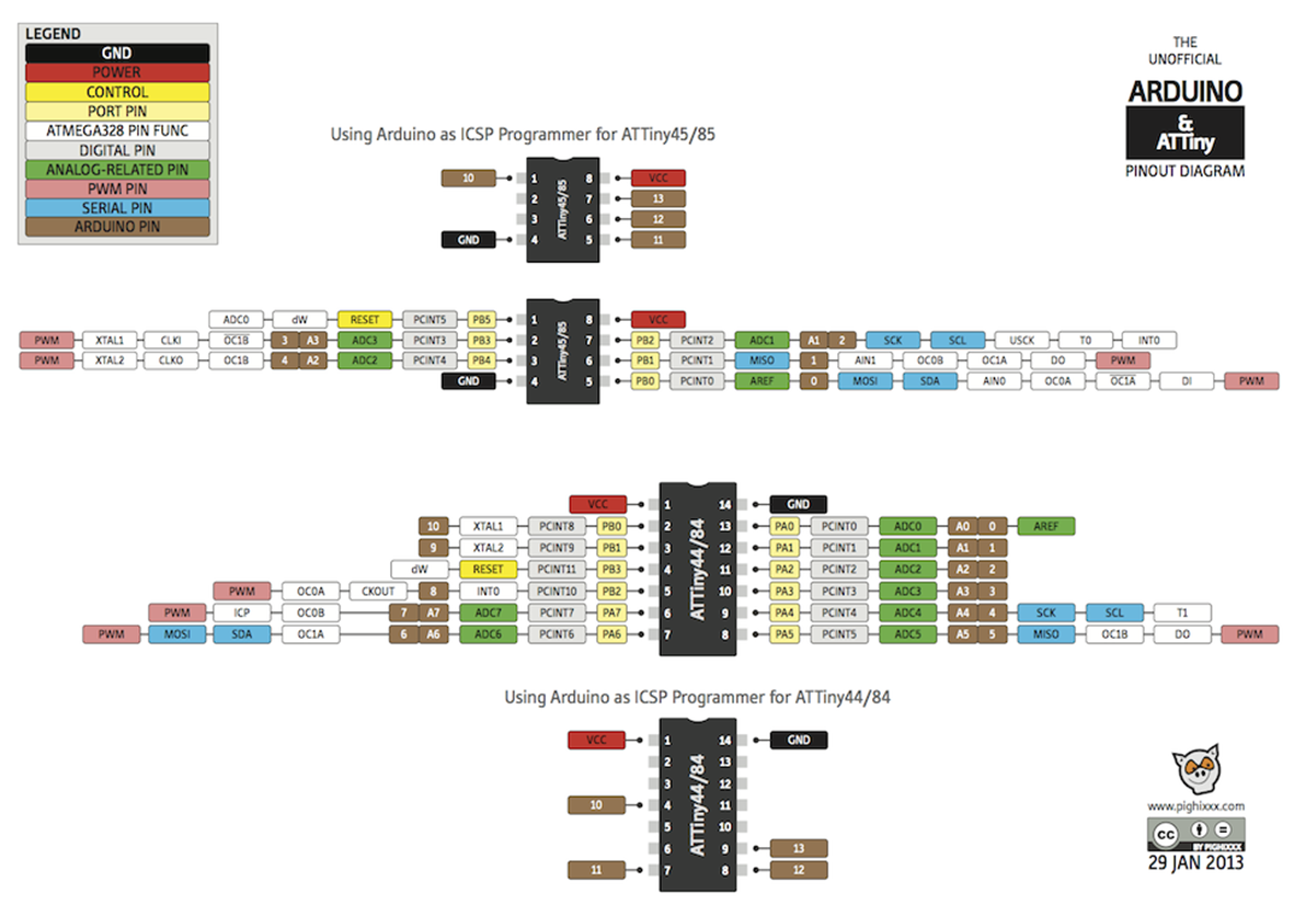
Emma seemed to be quite sure that this was not caused by something that I did wrong so the only choice I had was to digest that I would only connect it to the computer for a very limited time and only to load code. With that thought, I burned the bootloader through Arduino IDE and by going to 'Tools' with the following settings:
- Board: ATtiny
- Processor: ATtiny45
- Clock: 1MHZ (internal)
- Programmer: USBTiny ISP
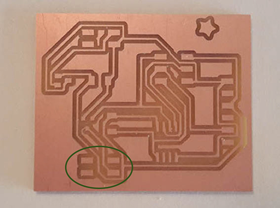
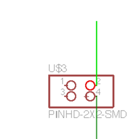
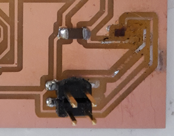
Tuesday 03/05/16: There was something that was worrying me overnight and that was the fact that Jacopo had noticed that there was only one trace ending on my connectors. This meant that either Power or Gnd were missing. When I showed it to Emma we checked the schematic where I realized that I forgot to label one of the wires.
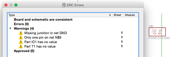
When running the ERC command I remembered that I had done that myself but I decided to ignore the warning 'Missing junction in net GND'. And I can't believe that I did that! I shall not be ignoring important warnings in the future.
Thankfully it was something that it was easily solvable as one can see from the image above. On one of my two boards I even solved it by only adding some solder. On the second one I had to add a small piece of wire.
Since I believed that the board was operable and I had soldered new wires with female connectors on my speaker I 'borrowed' anArduino code from Shirley Niemans' fab website just to make sure that my board worked. Once I had the board operating I was going to spend the rest of my day coding so I could cover what I had missed from the Input Week as well: 'Implement and interpret programming protocols'.
Although I easily managed to upload the code despite the issue with the over-heating regulator, my plans about the coding did not flourish because I spent the afternoon debugging the board.
From the first moment of uploading, I could only hear the sound but only very faintly. At the same time the regulator kept over-heating with the battery as well.
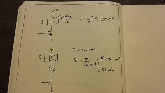
Firstly I changed the regulator, then I took it out completely to be able to connect to the board directly to the computer (onto 5.5V). Both actions provided the same faint sound signal. Then I added a 50Ohm resistor to the speaker with which I managed to control the over-heating but not produce decently audible sound. I changed to a 23Ohm Resistor which again made the regulator over-heat without any changes in the quality of the sound. After that I changed the speaker without positive results.
While I was doing that, however, the speaker connections accidentally touched a pin of the FTDI connector, which to my suprise, provided me with the sound level that I needed…! Emma and I were then discussing what changes and re-wiring to do in order to make work, but I had to step up and insist that we should check the pin number assignment! I really didn't trust that I had assigned it correctly and I suddenly remembered that naming the wrong microcontroller pin had given me a very faint LED light in Embedded Programming Week.
We assigned the pin number to '1', sent the code again and finally got the right level of sound. I hereby insist that today I have made an important contribution towards the electronics industry by discovering that assigning the wrong pin number in the Arduino IDE may in fact make your device work, but will be giving it too little strength.
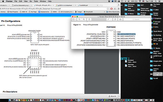
I need to admit, that going from the schematic to understanding the board is still somewhat confusing to me, so are datasheets.Although things are becoming clearer every week that we work with them, I still feel that I am climbing a very steep hill and I am dreading what is to come in the last two electronics weeks!

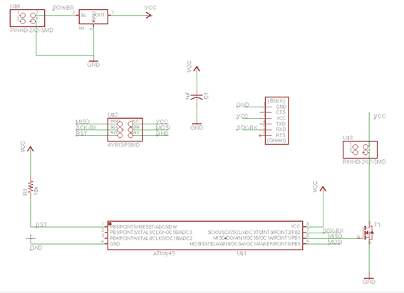
I also begun to understand the image above, so it's about time I start putting it to good use. Click here to download it.
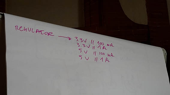
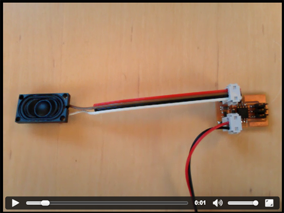
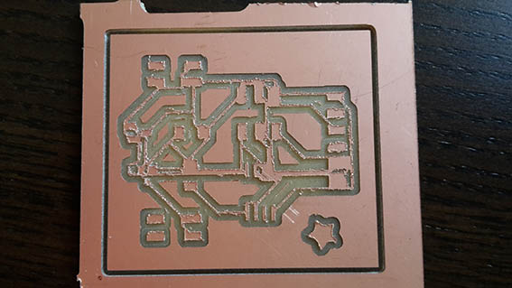
For this week I have made two operable boards. On the second one I uploaded the Arduino code from Emma Pareschi's fab website I feel more confident working on two boards at a time as it gives me more chances of submitting the deliverables and I sincerely don't think that it is consuming a lot of my time. Despite my plans of devoting more time to code, I have sadly ran out of time. I remain hopeful that I will catch up with it soon. Below you can see (and hear!) the video from my successful hello speaker attempt. I will also attempt to fix the over-heating issue since I now have an understanding of it. The regulator I used was a 100mA one, but I should probably have used the 1Amp one (1000mA). I will try to replace it and update this page soon.
After the local review, I devoted some time to changing the regulator. I tried to replace it by adding wires between the pads and the actual 1Amp regulator. The previous one was about three times smaller than the one I had to fix now, so it was impossible to attach it exactly in it's place. I checked it's orientation on it's datasheet that I found on the internet and I proceeded with de-soldering the previous one in order to attach the larger one.
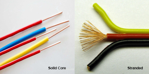
Unfortunately the first wire that I tried to use was stranded-core wire which made my life very difficult. I did manage to solder it, however, and at some point the regulator stopped heating up. Although I tried to achieve this again, I failed, most probably because of a short in the wires. I de-soldered them and attempted to solder new solid-core wires.
By then, the pads which were already very small and worn out, simply broke off and there was no room to attach anything. I now need to mill a new board specifically designed with the 1Amp regulator in mind to see if I can solve the issue…
Thankfully I still have my second board which operates fine, so I proceeded to play a little bit with programming/loading a different tune. This was a little bit tricky because I could not get it to play at a high tempo. When the tempo setting was high, I would get the first notes right and then there would only be noise. You can hear this in the video below. When I lowered the value of the tempo, the tune was way too slow, but it played until the end.
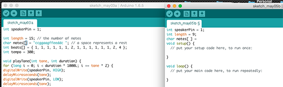
I had based my new tune on the code that I found on Shirley Nieman's website. She actually got to hear her own tune played by my board and said that it was very slow… Now I assume that both of those issues have to do with the fact that I set the internal clock to 1MHz while burning the bootloader, so the capabilities of the microcontroller in terms of rhythm are restricted! Nevertheless, you can find the Arduino code file (as well as all other related files) below.
Arduino Slow Tune - File Eagle Schematic - File Eagle Board - File Image - File Border - File Output Devices Lecture Back to Weekly Assignments Home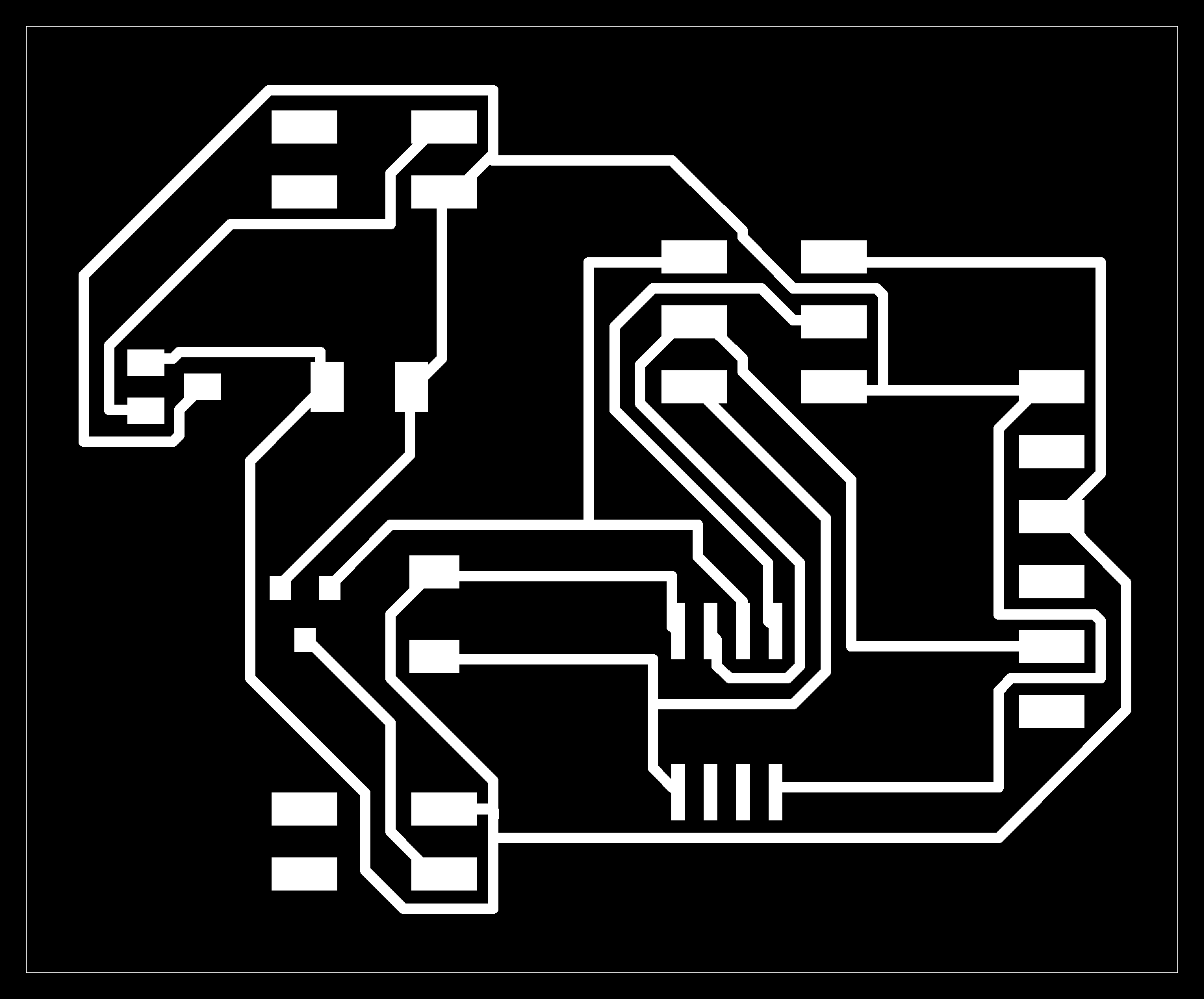